


HID Aero X100
Door & Reader
Interface Module
Host & intelligence
RS-485
Expands door count
4 × OSDP per X100
per X100 module
© HID Global Corporation / ASSA ABLOY AB
HID Aero X100 — What It Is and How It Works
The Door/Reader Interface IO Module that scales the HID Aero X1100 beyond 2 doors — adding up to 2 access points per module, with full AES-256 encryption on all module communication
The HID Aero X100 is a Door/Reader Interface IO Module from HID Global, designed to expand the door capacity of an HID Aero X1100 intelligent controller. On its own, the X1100 manages 2 access points — attach one or more X100 modules via RS-485 and each one adds another 2 access points to the system, up to a total of 64 access points from a single X1100.
Each X100 provides on-board support for up to 2 access points with either 2 Wiegand/Clock & Data readers or up to 4 OSDP readers. Four robust relays handle door lock and auxiliary output control, while 7 supervised inputs monitor door status, REX (Request to Exit), power supply, battery, tamper, and general-purpose signals — all with 4-state analogue-to-digital conversion.
The X100 is the direct replacement for the HID VertX V100 IO module, sharing the same physical footprint and RS-485 wiring compatibility. The key security improvements in the Aero X100 over the VertX V100 are AES-256 encryption between the X100 and the X1100 controller, OSDP secure channel reader support, and crypto chip protection for stored keys and passwords.
- Attaches to HID Aero X1100 intelligent controller via RS-485
- Can also be chained — multiple X100s daisy-chained on the same RS-485 bus
- Each X1100 IO Module port supports up to 32 Aero X100 modules
- Compatible with existing HID VertX RS-485 wiring
- Same physical footprint as HID VertX V100 — fits in same enclosure/panel
// Quick Reference — HID Aero X100
X100 Requires an X1100 — It's Not a Standalone Controller
The HID Aero X100 is an IO expansion module — it does not contain its own intelligence or network connectivity. It must be attached to an HID Aero X1100 intelligent controller via RS-485 to function. The X1100 provides all access control processing, network communication, and decision-making; the X100 simply adds more reader ports, inputs, and relay outputs within the X1100's reach.
Key Benefits of the HID Aero X100 Module
Why the HID Aero X100 is the right IO module for expanding door capacity in new and existing HID Aero / VertX deployments
Expand Doors Without Changing the Controller
Each X100 module adds 2 more access points to the X1100 system. Attach additional X100s as your premises grow — no controller replacement needed.
- 2 access points per X100 module
- Up to 32 X100 modules per X1100 RS-485 port
- Two RS-485 ports on the X1100 — up to 64 modules total
- Maximum system capacity: 64 access points from one X1100
AES-256 Encrypted Module Communication
All communication between the HID Aero X100 and the X1100 controller is protected with AES-256 encryption — preventing interception on the RS-485 module bus.
- AES-256 encryption on RS-485 module communication bus
- Crypto chip protects stored keys and passwords on-board
- End-to-end security from reader to host — no unencrypted links
- Significant security upgrade over legacy VertX V100
Direct VertX V100 Replacement
The Aero X100 fits in the same physical footprint as the HID VertX V100, uses the same RS-485 wiring, and communicates with the X1100 using existing VertX cable runs.
- Same form factor as VertX V100 — fits in the same panel
- Existing VertX RS-485 wiring is fully reusable
- No new cabling required for V100 → X100 upgrades
- Protect your existing VertX infrastructure investment
OSDP Reader Support with Secure Channel
Support up to 4 OSDP readers per X100 module — with OSDP secure channel providing encrypted, bidirectional communication between the module and HID Signo or other OSDP readers.
- Up to 4 OSDP readers in multi-drop configuration per module
- OSDP secure channel — fully encrypted reader communication
- Bidirectional communication for reader feedback and configuration
- Compatible with HID Signo and all OSDP-certified readers
Full Input Monitoring — 7 Supervised Inputs
Seven supervised inputs per X100 module monitor all door hardware signals with 4-state analogue-to-digital conversion for highly reliable status detection.
- 7 supervised inputs: door status, REX, power, battery, tamper
- 4-state detection: open, closed, short, tamper (with ADC)
- Configurable as supervised or unsupervised per input
- Custom EOL resistances configurable via host software
4 High-Amp Relays per Module
Four robust high-amp relays provide reliable door lock and auxiliary output control at each X100 module — protecting the circuit from power-hungry strike and lock hardware.
- 4 relays (RELAY 1–4) per module
- High-amp rated for wider choice of door lock hardware
- NO and C terminals for DC strike and auxiliary alarm wiring
- Fuse recommended in the relay circuit for protection
HID Aero X100 — Available Variants
The X100 family includes two variants — standard X100 and the X100A (Variant B) — both providing the same door/reader interface capability
HID Aero X100
Standard Door/Reader Interface Module
- 2 access points on-board
- Up to 4 OSDP or 2 Wiegand readers
- 7 supervised inputs with 4-state ADC
- 4 high-amp relays
- 1 RS-485 port for daisy-chaining
- AES-256 encryption to X1100 controller
- OSDP secure channel support
- Crypto chip key protection
- DIN rail compatible mounting
- Direct replacement for HID VertX V100
HID Aero X100A (Variant B)
Input Monitor Interface Module — Variant B
- Same hardware specification as X100
- 2 access points, 4 readers, 7 inputs, 4 relays
- Different terminal / connector configuration (Variant B)
- AES-256 encryption — same as X100
- OSDP secure channel — same as X100
- Used where Variant B physical layout is required
- Interchangeable with X100 in software configuration
Which Variant Should You Order?
The X100 and X100A (Variant B) provide the same access control capability and security. The difference is physical — the Variant B has a different connector and terminal layout suited to specific panel configurations. Consult Cybernetics Software to confirm which variant is appropriate for your enclosure and installation design before ordering.
HID Aero X100 — Full Technical Specifications
Complete specification reference for the HID Aero X100 Door/Reader Interface Module
Power & Supply
| Input Voltage | 12 to 24 V DC ±10% |
| Power Cable | Minimum 18 AWG wire |
| Power Source Requirement | Must be powered from a UL294 Certified limited power source output |
| Power & Relay Cable | 2-conductor shielded, 18–16 AWG — max 500 ft (150 m) |
Reader Support
| OSDP (RS-485) Readers | Up to 4 (multi-drop per module) |
| Wiegand / Clock & Data Readers | Up to 2 (per module) |
| OSDP Secure Channel | Supported — encrypted, bidirectional reader communication Security |
| OSDP Cable | Two 2-conductor cables: one power (18 AWG), one data (24 AWG shielded twisted pair) |
| OSDP Max Length | Up to 200 ft (61 m) without termination resistor; install 120Ω ±2Ω for longer runs or EMF environments |
| Wiegand / C&D Cable | 4-conductor, 18 AWG, shielded — max 500 ft (150 m) |
| Compatible Readers | HID Signo (OSDP), all standard Wiegand / Clock & Data readers |
Access Point Capacity
| On-Board Access Points per X100 | 2 |
| Maximum X100 Modules per X1100 RS-485 Port | 32 |
| Total X100 Modules (2 ports × 32) | 64 Aero modules maximum |
| Total System Capacity (X1100 + X100s) | 64 access points, 64 readers, 615 inputs, 388 outputs |
Inputs
| On-Board Supervised Inputs | 7 per module |
| Input Types Monitored | Door status, REX (Request to Exit), power supply, battery, tamper, general-purpose |
| Supervision Type | 4-state (open, closed, short, tamper) with analogue-to-digital conversion |
| Unsupervised Configuration | Normally open or normally closed contacts directly — no EOL resistors needed |
| Supervised Configuration | Requires two 1kΩ, 1% resistors placed close to the sensor |
| Custom EOL Resistances | Configurable via host access control software |
| Alarm Input Cable | One twisted pair, typically 22 AWG — max 1,000 ft (304.8 m); up to 30 inputs on one run |
Outputs & Relays
| On-Board Relays | 4 per module (RELAY 1 to RELAY 4) |
| Relay Type | High-amp relays for door lock and auxiliary output control |
| Relay Terminals Used | NO (Normally Open) and C (Common) — typical for DC strike control |
| Fuse Requirement | Fuse recommended in circuit between DC power source and relay |
| Power & Relay Cable | 2-conductor shielded, 18–16 AWG — max 500 ft (150 m) |
RS-485 IO Module Connection
| RS-485 Port | 1 port — for connection to X1100 and daisy-chaining to further X100/X200/X300 modules |
| RS-485 Cable Type | 1 twisted pair, shielded, 120Ω impedance, 24 AWG |
| RS-485 Maximum Cable Length | 4,000 ft (1,219 m) |
| RS-485 Termination | Install 120Ω ±2Ω termination resistor at devices at EACH END of the bus only; do not install on intermediate modules |
| Module Encryption | AES-256 on all communication between X100 and X1100 Security |
| VertX RS-485 Wiring | Compatible — existing VertX V100 RS-485 wiring can be reused |
Security Features
| IO Module Encryption | AES-256 — all RS-485 communication between X100 and X1100 controller |
| Reader Communication | OSDP Secure Channel — encrypted, bidirectional |
| Key Protection | Crypto chips protect stored keys and passwords from malicious attacks |
| Supervised Input Monitoring | 4-state detection identifies system faults or malicious attacks on wiring |
Physical & Mounting
| Form Factor | Same physical footprint as HID VertX V100 |
| Mounting | Standard panel mounting; DIN rail compatible with USA 10 Series Rail Adapter (part no. 1201578) |
| VertX Footprint Compatible | Yes — fits in the same enclosure/panel as HID VertX V100 |
| Regulatory Compliance | FCC (USA), ICES-003 (Canada), CE Mark (Europe), RCM Mark (Australia/NZ) |
| Installation Standards | All National and local Electrical Codes; NFPA70 (NEC) compliant installation required |
VertX V100 Replacement Information
| Replaces | HID VertX V100 Door/Reader Interface Module |
| Physical Footprint | Same as VertX V100 — direct physical replacement |
| RS-485 Wiring Compatibility | Existing VertX V100 RS-485 wiring is fully compatible with X100 |
| Security Improvements over V100 | AES-256 IO module encryption, OSDP secure channel, crypto chip protection — all new in X100 |
HID Aero X100 — Connection Diagram
How the X100 connects to readers, door hardware, inputs, relays, and the X1100 controller via RS-485
HID Aero X100 Connection Diagram
Reader ports, relay wiring, supervised inputs, and RS-485 module port connections
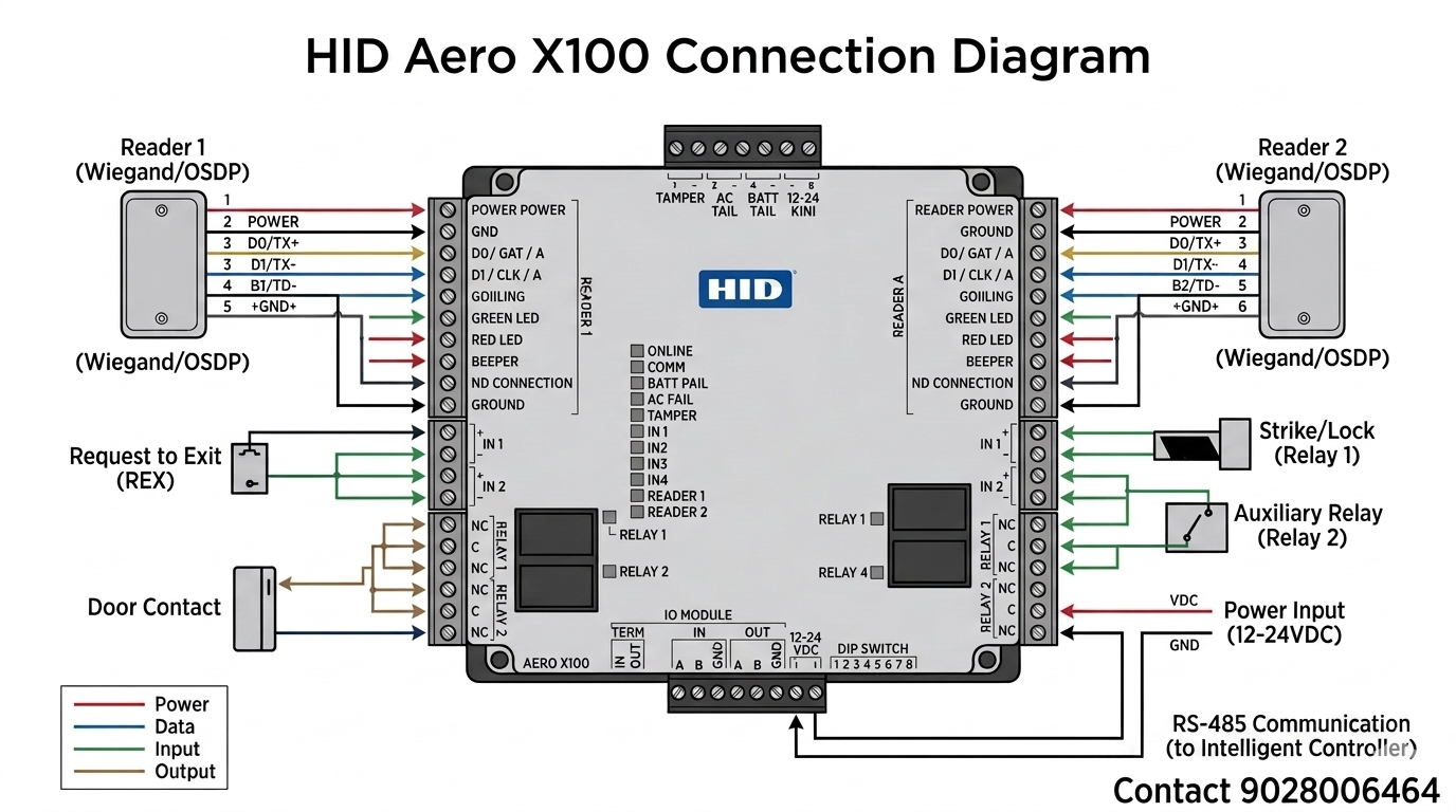
RS-485 to X1100Connection to the X1100 intelligent controller IO Module port — or to the previous X100 module in a daisy-chain
Reader Ports 1 & 24-conductor 18 AWG shielded for Wiegand, or two 2-conductor cables for OSDP (power + data)
Relay Outputs 1–4NO and C terminals wired to DC strike + fuse + DC power source for door lock control
Power Input12–24 V DC ±10%, minimum 18 AWG wire. Connect TAMPER monitoring if cabinet supervision required
Supervised Inputs 1–71 twisted pair, 22 AWG, max 1,000 ft. Configure EOL resistors (1kΩ/1kΩ) near sensor for supervised mode
RS-485 to Next ModuleContinue daisy-chain to next X100, X200, or X300 module. Install 120Ω termination at final device in chain only
RS-485 Termination — Critical Installation Note
When daisy-chaining multiple X100 (or other Aero IO) modules along the RS-485 bus, install the 120Ω termination resistor ONLY at the two devices at each physical end of the bus — the X1100 at one end, and the last IO module in the chain at the other end. Installing termination resistors on intermediate modules will degrade RS-485 signal integrity and cause unreliable communication between the X1100 and its IO modules.
HID Aero X100 — Complete Wiring Reference
Cable types, maximum lengths, and connection guidance for each interface on the HID Aero X100 module
Power Supply
// 12–24 V DC INPUT
- Input: 12–24 V DC ±10%
- Minimum wire gauge: 18 AWG
- Must be powered from UL294 Certified limited power source
- Power and relay cable: 2-conductor shielded, 18–16 AWG, max 500 ft (150 m)
- Observe polarity on 12–24 V DC input connection
- Multiple earth ground connections may cause interference — use single common ground
Reader Connections
// READER PORT 1 & 2 (Wiegand / OSDP)
- Wiegand / C&D: 4-conductor, 18 AWG, shielded — max 500 ft (150 m)
- Optional additional conductors for LED and beeper control
- OSDP: two 2-conductor cables — one 18 AWG for power, one 24 AWG shielded twisted pair for data
- OSDP max length: 200 ft (61 m) without termination; install 120Ω ±2Ω for longer runs or EMF environments
- Readers requiring different voltage or high current must be powered separately
Relay / Door Strike
// RELAY 1–4 (door lock control)
- 4 relays for door lock mechanisms or alarm signalling
- Use NO (Normally Open) and C (Common) terminals for DC strike
- Wire: DC power source → Fuse → RELAY NO terminal → door strike
- Fuse must be installed in the relay circuit for protection
- Power and relay cable: 2-conductor shielded, 18–16 AWG, max 500 ft (150 m)
Supervised Inputs
// IN 1–4 / door status, REX, alarm
- Cable: 1 twisted pair, 22 AWG — max 1,000 ft (304.8 m); max 30 inputs per run
- Unsupervised: connect NC or NO contact directly — no EOL resistors needed
- Supervised: install two 1kΩ, 1% resistors placed close to the sensor device
- Custom EOL resistances can be set via host access control software
- Standard EOL: 1kΩ/1kΩ, 1%, 1/4 watt
RS-485 Module Port
// Connection to X1100 and daisy-chain
- Cable: 1 twisted pair, shielded, 120Ω impedance, 24 AWG
- Maximum run: 4,000 ft (1,219 m) total bus length
- Connect to X1100 IO Module Port 1 or 2, or to the RS-485 port of the previous module in chain
- Continue daisy-chain to next X100/X200/X300 from the other RS-485 terminal
- Install 120Ω termination resistor only at the TWO physical ends of the complete bus
HID Aero X100 Status LED Reference
LED indicators on the X100 module for on-site diagnostics and commissioning
READER 2 LED
ON for approximately 1 second at power-up. OSDP mode: flashes when transmitting data. Wiegand/C&D mode: flashes when data is received on either reader input.
RELAY 1–4 LEDs
OFF = Relay de-energised (normal rest state). ON = Relay energised — door strike is powered / output is active.
IO Communication LED
Indicates RS-485 communication activity between the X100 module and the X1100 controller. Active flashing confirms the module is communicating successfully.
INPUT LEDs
Each supervised input LED reflects its current state. If a defined input is active, the LED pulses to its opposite state every 3 seconds (0.1 second pulse). Otherwise LED is OFF.
Frequently Asked Questions — HID Aero X100
Technical and procurement questions about the HID Aero X100 Door/Reader Interface Module
What is the HID Aero X100?
What is the difference between the HID Aero X100 and the HID VertX V100?
Can the HID Aero X100 work without an X1100 controller?
How many HID Aero X100 modules can connect to one X1100?
What is the maximum RS-485 cable length for the HID Aero X100?
Can existing HID VertX V100 wiring be reused with the HID Aero X100?
Need HID Aero X100 Modules for Your Project?
Cybernetics Software is an authorised HID Global NAS partner. We supply HID Aero X100 modules, design the complete access control system, install, and provide ongoing support — across Pune and pan India.
+91-9028006464